Fuse box diagram (fuse layout), location, and assignment of fuses and relays Ford Transit Connect (2010, 2011, 2012, 2013).
Checking and Replacing Fuses
Fuses and circuit breakers protect your vehicle's electrical system from overloading. If electrical parts in your vehicle are not working, the system may have been overloaded and blown a fuse or tripped a circuit breaker. Before you replace or repair any electrical parts, check the appropriate fuses or circuit breakers.
To check a fuse, look at the silver-colored band inside the fuse. If the band is broken or melted, replace the fuse.
Notice
- Before replacing fuses check that the key has been removed from the ignition and that all the services are switched off and/or disengaged.
- Always disconnect the battery before servicing high current fuses.
- Always replace a fuse with one that has the specified amperage rating. Using a fuse with a higher amperage rating can cause severe wire damage and could start a fire.
- Never replace a broken fuse with anything other than a new fuse. Use always an intact fuse of the same color.
- If a fuse blows again contact a qualified service center.
Passenger Compartment Fuse Box
Left-hand drive: the fuse panel and relay box are located behind the cover to the left of the steering wheel.
Right-hand drive: the fuse panel is behind the glove box.
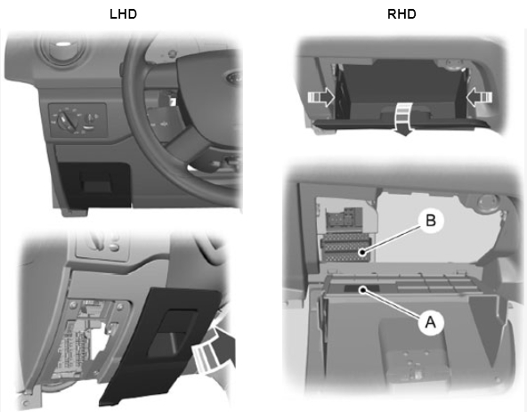
- A) Fuse Chart Label
- B) Fuses
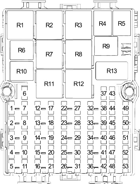
| № | A | Protected Component |
|---|---|---|
| 1 | 15 | Generic Electronic Module (GEM) (Hazard Flashers) |
| 2 | 5 | Exterior Rear View Mirror Switch |
| 3 | 10 | Main Light Switch, Generic Electronic Module (GEM) |
| 4 | - | - |
| 5 | - | - |
| 6 | 10 | Light Switch, Daytime Running Lamps (DRL) |
| 7 | 15 | Generic Electronic Module (GEM), Horn/Battery Saver |
| 8 | 7.5 | Audio Control Module (ACM), Radio, Instrument Cluster (IC), Tire Pressure Monitoring System (TPMS) Module |
| 9 | 10 | 2011-2013: Reversing Lamps Relay |
| 10 | 20 | Ignition Supply, Block Connector (Taxi) |
| 11 | - | - |
| 12 | 10 | 2009-2010: Main Light Switch |
| 7.5 | 2011-2013: Main Light Switch, Front/Rear Fog Lamps | |
| 10 | 2011-2013: Main Light Switch, Front/Rear Fog Lamps, Heated Front Washer Jets | |
| 13 | 15 | Brake Pedal Position Switch |
| 14 | 15 | Cigar Lighter (Front) |
| 20 | Cigar Lighter, Front Power Point | |
| 15 | 10 | Ignition Supply, Block Connector (Taxi) |
| 16 | - | - |
| 17 | 20 | Front Wiper Relay, Generic Electronic Module (GEM), Windshield Wiper Motor |
| 18 | 15 | 2011-2013: Front Fog Lamps Relay |
| 10 | Heated Front Seats | |
| 19 | 7.5 | Generic Electronic Module (GEM), Instrument Cluster (IC), Recirculation |
| 20 | 10 | Block Connector (Taxi), Ignition Supply/Battery Supply |
| 21 | - | - |
| 22 | 15 | Audio Control Module (ACM), Speech Recognition Module (SRM), Radio, Bluetooth/Voice Command Module |
| 23 | 7.5 | A/C Switch, Parking Aid Module (PAM) |
| 24 | 7.5 | Interior Lamps Relay, Battery Saver |
| 25 | 15 | Taxi Roof Lamp Switch |
| 26 | 10 | 2011-2013: Battery Saver |
| 27 | 7.5 | Right Rear Marker Lamp, Right Rear Lamp Assembly, Right Front Side Lamp, Right Headlamp Assembly |
| 28 | 7.5 | License Plate Lamps |
| 29 | 10 | Main Light Switch, Rain Sensor |
| 30 | 20 | Auxiliary Blower Motor |
| 31 | - | - |
| 32 | 7.5 | Anti-lock Brake System (ABS) Module, ESP, Steering Angle Sensor Module |
| 33 | 7.5 | Occupant Classification System Module (OCSM), Passenger Air Bag Deactivation (PAD) indicator, Restraints Control Module (RCM) |
| 34 | 20 | Generic Electronic Module (GEM), Power Door Lock, Rear Door Unlock Relay |
| 35 | 20 | 2011-2013: Tire Pressure Monitoring System (TPMS) Module |
| 36 | - | - |
| 37 | 25 | Front Power Windows, Master Window Control Switch, One-Touch Down Window Relay |
| 38 | 7.5 | Rear Window Defroster/Heated Mirror Switch |
| 39 | 10 | Daytime Running Lamps, Parking Lamps, Number Plate Lamp |
| 40 | 15 | Power Point |
| 20 | Second Power Point | |
| 41 | - | - |
| 42 | - | - |
| 43 | 10 | 2011-2013: Right Rear Turn Relay |
| 44 | 10 | 2011-2013: Left Rear Turn Relay |
| 45 | 15 | 2009-2010: Rear Power Point |
| 20 | 2011-2013: Rear Power Point, Rear Center Console Power Point, Transco Hand Wash | |
| 46 | 7.5 | Left Rear Marker Lamp, Left Rear Lamp Assembly, Left Front Side Lamp Left Headlamp Assembly |
| 47 | - | - |
| 48 | - | - |
| 49 | 25 | Rear Window Defrost Grids |
| 50 | 7.5 | Generic Electronic Module (GEM), Instrument Cluster (IC), Passive Anti-Theft Transceiver, Tire Pressure Monitoring System (TPMS) Module, Rear View Camera, Rear View Camera Display Mirror, Accelerator Pedal |
| 51 | 20 | Generic Electronic Module (GEM), Wiper/Washer Switch, Rear Wiper Motor Assemblies |
| 52 | - | - |
| 53 | - | - |
| | ||
| R1 | - | |
| R2 | - | |
| R3 | - | |
| R4 | Interior Light | |
| R5 | Front Wiper | |
| R6 | Low Beam Interrupt | |
| R7 | Rear Window Defogger | |
| R8 | 2011: Battery Saver | |
| 2011-2013: Ignition | ||
| R9 | Rear Door Unlock | |
| R10 | 2011-2013: Front Fog Light | |
| Auxiliary Blower Motor | ||
| R11 | Blower Motor | |
| R12 | 2011-2013: Battery Saver | |
| R13 | - | |
Engine Compartment Fuse Box
The power distribution box is located in the engine compartment. The power distribution box contains high-current fuses that protect your vehicle's main electrical systems from overloads.
Note: To remove the power distribution box cover, the battery negative cable clip needs to be removed first. Pull up on the clip to detach it from the battery tray.
Diagram (Type 1)
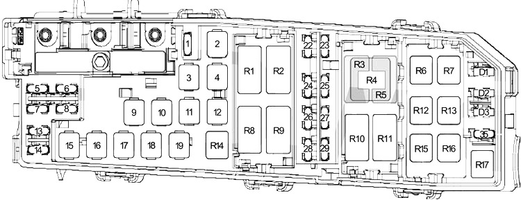
| № | A | Protected Component |
|---|---|---|
| 1 | 7.5 | Heated Windshield Telltale |
| 25 | Rear Fan Relay, Fuses (Passenger Compartment): No. 10, 15 | |
| 2 | 40 | 2009-2010: Fuses (Passenger Compartment): No. 12, 13, 17, 20, 30, 37, 51 |
| 40 | 2011-2013: Right Heated Windshield | |
| 3 | 20 | 2009-2010: Ignition Switch |
| 50 | 2011-2013: Left Heated Windshield | |
| 50 | Block Connector (only Taxi) | |
| 4 | 20 | Fuel Pump Relay |
| 5 | 10 | Keep Alive Power (PCM), Evaporative Emission (EVAP) Canister Vent Control Solenoid |
| 6 | 15 | Generator, Data Link Connector (DLC) |
| 7 | 10 | 2009-2010: Reverse Lamp Relay |
| 20 | 2011-2013: Ignition Switch | |
| 8 | 15 | High Beam Relay |
| 9 | 40 | 2009-2010: Fuses (Passenger Compartment): No. 1, 2, 3, 14 |
| 40 | 2011-2013: Fuses (Passenger Compartment): No. 7, 19, 22, 25, 34, 40, 45 | |
| 10 | 30 | 2009-2010: Fuses (Passenger Compartment): No. 7, 19, 22, 25, 34, 40, 45 |
| 25 | 2011-2013: Fuse (Passenger Compartment): No. 20, Auxiliary Rear Motor Relay | |
| 30 | 2011: Fuse (Passenger Compartment): No. 20, Left Turn Relay (Taxi), Right Turn Relay (Taxi) | |
| 11 | 30 | 2009-2011: Starter Relay |
| 40 | 2011-2013: Ignition Relay | |
| 12 | 30 | Anti-Lock Brake System (ABS) Module / Roll Stability Control (RSC) Pump Motor |
| 13 | 30 | Blower Motor Relay |
| 14 | 10 | Powertrain Control Module (PCM) Power Relay |
| 15 | 20 | Anti-Lock Brake System (ABS) Module / RSC |
| 16 | 30 | Low Speed Fan Control Relay |
| 17 | 50 | High Speed Fan Control Relay |
| 18 | 20 | 2009-2010: Daytime Running Lamps Relay, Low Beam Interrupt Relay |
| 25 | 2011-2013: Daytime Running Lamps Relay, Low Beam Interrupt Relay | |
| 19 | 20 | 2009-2010: Tire Pressure Monitoring System (TPMS) Module |
| 50 | 2011-2013: Rear Window Defogger Relay, Fuses (Passenger Compartment): No. 1, 2, 3, 9, 14, 25, 35 | |
| 22 | 10 | Fuel Injectors, Powertrain Control Module (PCM), Auxiliary Connector |
| 23 | 10 | Right Low Beam |
| 24 | 10 | A/C Clutch Relay |
| 25 | 10 | Left Low Beam |
| 26 | 10 | Evaporative Emission (EVAP) Canister Purge Valve, Heated Oxygen Sensor (HO2S), Reverse Lamp Relay, Exhaust Gas Recirculation (EGR) Stepper Motor, Mass Air Flow/intake Air Temperature (MAF/IAT) Sensor, Transmission Range (TR) Sensor, Brake Pedal Position Switch, Floor Shifter |
| 27 | - | - |
| 28 | 15 | Powertrain Control Module (PCM) |
| 29 | 15 | Coil on Plugs, Auxiliary Connector |
| 35 | 10 | 2009-2010: Powertrain Control Module (PCM) |
| 30 | 2011-2013: Starter Lock Relay | |
| | ||
| R1 | 2009-2011: Ignition | |
| 2011-2013: Right Heated Windshield | ||
| Auxiliary Blower Motor | ||
| R2 | 2011-2013: Starter Lock | |
| R3 | - | |
| R4 | High Speed Fan Control | |
| R5 | - | |
| R6 | Reverse Light | |
| R7 | Fuel Pump | |
| R8 | High Beam | |
| R9 | Powertrain Control Module (PCM) Power | |
| R10 | Low Speed Fan Control | |
| R11 | 2009-2010: Starter | |
| 2011-2013: Left Heated Windshield | ||
| R12 | Daytime Running Light (DRL) | |
| R13 | Low Beam | |
| R14 | A/C Clutch | |
| R15 | Right Rear Turn (Taxi) | |
| R16 | 2011-2013: Front Fog Light | |
| R17 | Left Rear Turn (Taxi) | |
| | ||
| D1 | Cooling Fan | |
| D2 | Fuel Pump | |
| D3 | Start | |
Diagram (Type 2)
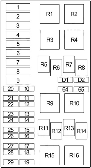
| № | A | Protected Component |
|---|---|---|
| 1 | 40 | Central Fuse Box |
| 2 | 30 | Double Cooling Fan |
| 3 | 30 | Central Fuse Box |
| 4 | 40 | Heated Windscreen |
| 5 | 40 | Single Cooling Fan |
| 50 | Double Cooling Fan (Main) | |
| 6 | 60 | Glow Plugs |
| 7 | 40 | Central Fuse Box |
| 8 | 20 | Ignition Switch |
| 9 | 20 | Engine Control Module (ECM) |
| 10 | 10 | Battery Voltage Sense, Data Link Connector |
| 11 | 20 | Fuel Fired Heater |
| 12 | 20 | Starter Solenoid |
| 13 | 30 | ABS Pump |
| 14 | 10 | Positive Crankcase Ventilation (PCV) Valve, Volume Control Valve (VCV) |
| 15 | 10 | Left High Beam |
| 16 | 10 | Left Low Beam |
| 17 | 10 | Right Low Beam |
| 18 | 10 | Powertrain Control Module (PCM) Power, Vehicle Speed Sensor |
| 19 | 20 | Daytime Running Lamps (Side Lights) |
| 20 | 1 | Powertrain Control Module (PCM) |
| 21 | 20 | Vaporizer Pump |
| 22 | 20 | Daytime Running Lamps (Dipped Beams) |
| 23 | 20 | ABS Valves |
| 24 | 10 | Glow Plug Monitoring (Diesel Engines) |
| 25 | 10 | Right High Beam |
| 26 | 10 | Air Conditioning Clutch Solenoid |
| 27 | 10 | Sensors, Actuators, Relay Coils |
| 28 | 20 | Foglamps |
| 29 | 20 | Dipped Beam (via Main Beam Relay) |
| 64 | 30 | Heater Blower Motor |
| 65 | 7.5 | Heated Windscreen |
| | ||
| R1 | Starter | |
| R2 | - | |
| R3 | Heated Windscreen | |
| R4 | - | |
| R5 | High Beam | |
| R6 | Low Beam | |
| R7 | Fuel Pump | |
| R8 | Engine/Powertrain Control Module (ECM/PCM) Power | |
| R9 | Glow Plugs | |
| R10 | - | |
| R11 | A/C | |
| R12 | Daytime Running Lamps | |
| R13 | Fuel Fired Heater | |
| R14 | Horn | |
| R15 | Cooling Fan | |
| R16 | Cooling Fan | |
| | ||
| D1 | - | |
| D2 | Cooling Fan | |
This website uses cookies to improve your experience. We'll assume you're ok with this, but you can opt-out if you wish. Cookie settingsACCEPT
Posted by: wallywallyescoeeer10264873.blogspot.com
Source: https://fusecheck.com/ford/ford-transit-connect-2010-2013-fuse-diagram
Post a Comment